A sand casting is also divided resin sand casting and green sand casting. sand casting is produced when molten metal is poured at atmospheric pressure into a cavity formed in a compacted molding sand. In typical ferrous casting, the mold would be bonded with 6 to 8 percent western bentonite mulled with 2 to 3 percent water. Patterns would be reusable, but the sand molds would be broken from the casting after the solidified casting had cooled sufficiently. The sand would be returned to the muller for recycling by mulling with some new clay and water to reactivate the old clay. Sand moulds define the external geometry of a casting, whereas cores define the interior or undercuts.

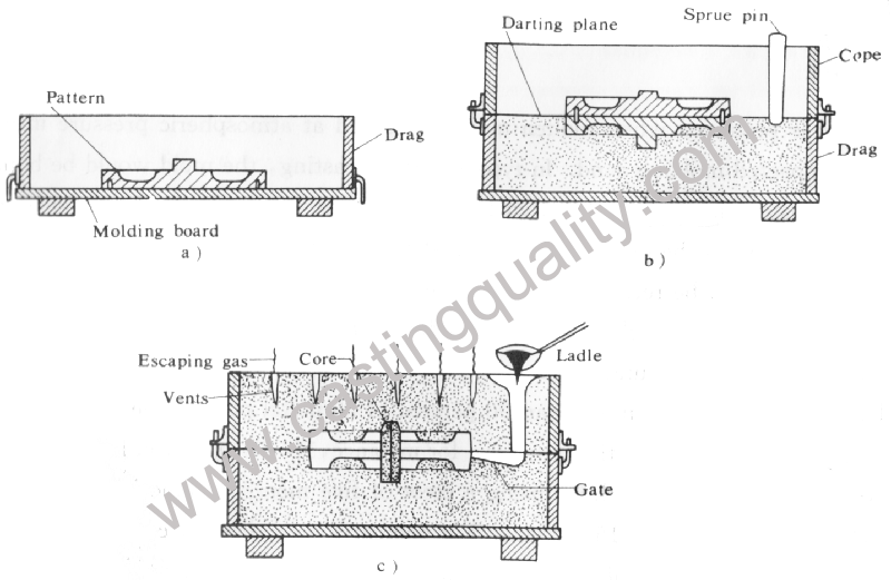
Fig 15.1 Procedure for making green sand casting molds
Sand casting accounts for more than 90 percent of all metal poured, on a tonnage basis. It can be an extremely high production process – for instance, 125Lb gray iron bathtubs are molded and poured at the rate of 72 and hour using a crew of five men. Automotive engine blocks are poured at the rate of one every 15 seconds. For comparison. a die cast engine block requires at least 2 minutes floor to floor time for one block.
On the other hand, the process of sand casting requires a high investment in plant facilities and sand handling equipment to make such production rates possible. Sand casting is versatile and is capable of making parts ranging from small knobs to huge radiotelescope bases weighing more than 200,000Lb.
A simple procedure of green sand casting for molding a cast iron gear blank is illustrated in Fig15.1. The mould for this blank is made in a flask that has two parts. The top part is called the cope and the lower part the drag. If the flask is made in three parts the center is called a cheek. The parts of the flask are held in definite relation to one another by pins on either side of the drag that fit into openings in angle clips fastened to the sides of the cope.
The first step in making a mould of sand casting is to place the pattern on a molding board that fits the flask being used. Next, the frag is placed on the board with the pins down( Fig.15.1a). Moulding sand fingers and the drag completely filled. Small molds are packed by a hand rammer, and mechanical ramming is used for large moulds and in high production molding. If the mold is not sufficiently rammed, it will fall apartwhen handled or when the molten iron strikes it, and if it is rammed too hard, steam and gas cannot escape when the molten metal enters.
After ramming has been completed, the excess sand is leveled off with a straight bar called a strike rod. To ensure the escape of gases whenthe casting is poured, small vent holes are made through the sand to within a fraction of an inch of the pattern.
The lower half of the mold is then turned over, so that the cope may be placed in positon and the mold finished. Before turning, a little sand is sprinkled over the mold and a bottom board placed on top. The drag is then rolled over and the molding board removed, exposing the pattern. The surface of the sand is smoothed over with a trowel and covered with a fine coating of dry parting sand. Parting sand is a fine grained, dry silica sand without strength. It prevents bonding of sand in the cope with sand in the drag.
Next, the cope is placed on the drag(Fig.15.1b). To provide a place for the iron to enter the mold, a tapered pin known as a sprue pin is placed approximately 1 in.(25.4mm) to one side of the pattern. The operations of filling, ramming, and venting the cope proceed in the same manner as in the drag.
At this point the mold is complete except for removal of the pattern and pattern and sprue pin. The sprue pin is first withdrawn and a funnel shaped opening is scooped out at the top, so that there will be a fairly large opening into which to pour the metal. The cope half of the flask is then care fully lifted off and set to one side. Before the pattern is withdrawn, the sand around the edge of the pattern is usually moistened with a swab, so that the edge of the mold hold firmly together when the pattern is removed. To loosen the pattern a draw spike is driven into it and rapped lightly in all directions. The pattern can then be withdrawn by lifting the draw spike.
Before the mold is closed, a small passage known as a gate must be cut bettween the cavity made by the pattern and sprue opening. This passage is shallowest at the mold, so that after the metal has been poured the metal in the gate may be broken off close to the casting. To allow for metal shrinkage, a howllow is sometimes cut into the cope, which provides a supply of hot metal as the casting cools, this opening is called a riser.
The mold surfaces maybe sprayed, swabbed, or dusted with a prepared coating material. Such coatings often contain silica flour and graphite, but their composition varies considerably depending on the material being cast. A mold coating improves the surface finish of the casting and reduces possible surface defects. The completed mold is shown in Fig.15.1c. Before the mold is poured, a weight should be put on top to prevent the hydrostatic pressure of the liquid metal from floating the cope and allowing metal to run out of the mold at the parting line.
